Our team of Positive Technologies researchers has delved deep into the internal architecture of Intel Management Engine (ME) 11, revealing a mechanism that can disable Intel ME after hardware is initialized and the main processor starts. In this article, we describe how we discovered this undocumented mode and how it is connected with the U.S. government's High Assurance Platform (HAP) program.
Disclaimer: The methods described here are risky and may damage or destroy your computer. We take no responsibility for any attempts inspired by our work and do not guarantee the operability of anything. For those who are aware of the risks and decide to experiment anyway, we recommend using an SPI programmer.
INTRODUCTION
Intel Management Engine is a proprietary technology that consists of a microcontroller integrated into the Platform Controller Hub (PCH) chip and a set of built-in peripherals. The PCH carries almost all communication between the processor and external devices; therefore Intel ME has access to almost all data on the computer. The ability to execute third-party code on Intel ME would allow for a complete compromise of the platform. We see increasing interest in Intel ME internals from researchers all over the world. One of the reasons is the transition of this subsystem to new hardware (x86) and software (modified MINIX as an operating system). The x86 platform allows researchers to make use of the full power of binary code analysis tools. Previously, firmware analysis was difficult because earlier versions of ME were based on an ARCompact microcontroller with an unfamiliar set of instructions.
Unfortunately, analysis of Intel ME 11 was previously impossible because the executable modules are compressed by Huffman codes with unknown tables. Nonetheless, our research team (Dmitry Sklyarov, Mark Ermolov, and Maxim Goryachy) managed to recover these tables and created a utility for unpacking images. The utility is available on our GitHub page: https://github.com/ptresearch/unME11.
After unpacking the executable modules, we proceeded to examine the software and hardware internals of Intel ME. Our team has been working on this for quite some time, and we have accumulated a large amount of material that we plan to publish. This is the first in a series of articles on the internals of Intel ME and how to disable its core functionality. Experts have long wondered about such an ability in order to reduce the risk of data leaks associated with any potential zero-day vulnerabilities in Intel ME.
HOW TO DISABLE ME
Some users of x86 computers have asked the question: how can one disable Intel ME? The issue has been raised by many, including Positive Technologies experts. [https://github.com/ptresearch/me-disablement/blob/master/How%20to%20become%20the%20sole%20owner%20 of%20your%20PC.pdf, https://hardenedlinux.github.io/firmware/2016/11/17/neutralize_ME_firmware_on_sandybridge_and_ivybridge.html]. And with the recently discovered critical (9.8/10) vulnerability in Intel Active Management Technology (AMT) (https://nvd.nist.gov/vuln/detail/CVE2017-5689), which is based on Intel ME, the question has taken on new urgency.
The disappointing fact is that on modern computers, it is impossible to completely disable ME. This is primarily due to the fact that this technology is responsible for initialization, power management, and launch of the main processor. Another complication lies in the fact that some data is hard-coded inside the PCH chip functioning as the southbridge on modern motherboards. The main method used by enthusiasts trying to disable ME is to remove everything "redundant" from the image while maintaining the computer's operability. But this is not so easy, because if built-in PCH code does not find ME modules in the flash memory or detects that they are damaged, the system will not start.
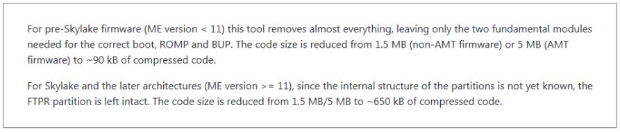
The me_cleaner project [https://github.com/corna/me_cleaner], in development for several years, has created a special utility for deleting most of the image and leaving only the components vital for the main system. But even if the system starts, the joy is short-lived—after about 30 minutes, the system may shut down automatically. The reason is that, after some failures, ME enters Recovery Mode, in which it can operate only for a certain period of time. As a result, the cleaning process becomes more complicated. For example, with earlier versions of Intel ME, it was possible to reduce the image size to 90 KB but the Intel ME 11 image can only be reduced to 650 KB.
SECRETS IN QRESOURCE
Intel allows motherboard manufacturers to set a small number of ME parameters. For this, the company provides hardware manufacturers with special software, including utilities such as Flash Image Tool (FIT) for configuring ME parameters and Flash Programming Tool (FPT) for programming flash memory directly via the built-in SPI controller. These programs are not provided to end users, but they can be easily found on the Internet.
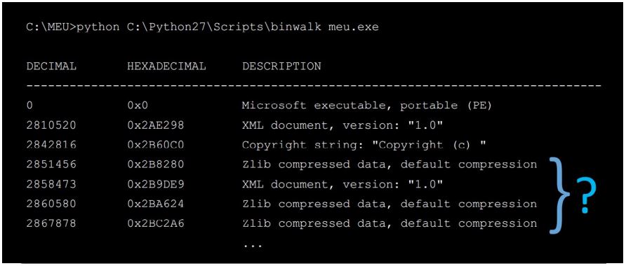
From these utilities, you can extract a large number of XML files (for a detailed description of the process, see https://www.troopers.de/downloads/troopers17/TR17_ME11_Static.pdf). These files contain a lot of interesting information: the structure of ME firmware and description of the PCH strap, as well as special configuration bits for various subsystems integrated into the PCH chip. One of the fields, called "reserve_hap", drew our attention because there was a comment next to it: "High Assurance Platform (HAP) enable".

Googling did not take long. The second search result said that the name belongs to a trusted platform program linked to the U.S. National Security Agency (NSA). A graphics-rich presentation describing the program can be found at http://fm.csl.sri.com/LAW/2009/dobry-law09-HAP-Challenges.pdf. Our first impulse was to set this bit and see what happens. Anyone with an SPI programmer or access to the Flash Descriptor can do this (on many motherboards, access rights to flash memory regions are set incorrectly).
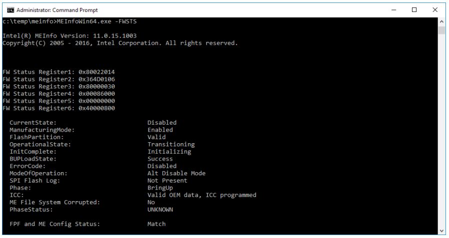
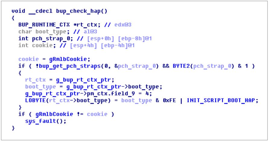
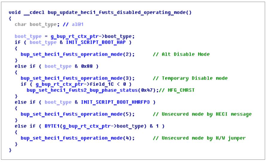
After the platform is loaded, the MEInfo utility reports a strange status: "Alt Disable Mode." Quick checks showed that ME did not respond to commands or react to requests from the operating system. We decided to figure out how the system goes into this mode and what it means. By that time, we had already analyzed the main part of the BUP module, which is responsible for initialization of the platform and sets the status displayed by MEInfo. In order to understand how BUP works, a more detailed description of the Intel ME software environment is necessary.
INTEL ME 11 ARCHITECTURE OVERVIEW
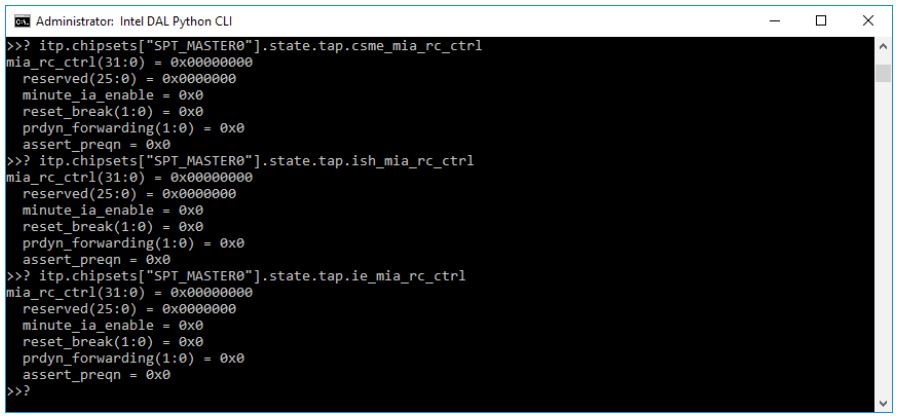
Starting with the PCH 100 Series, Intel has completely redesigned the PCH chip. The architecture of embedded microcontrollers was switched from ARCompact by ARC to x86. The Minute IA (MIA) 32-bit microcontroller was chosen as the basis; it is used in Intel Edison microcomputers and SoCs Quark and based on a rather old scalar Intel 486 microprocessor with the addition of a set of instructions (ISA) from the Pentium processor. However, for the PCH, Intel manufactures this core with 22-nm semiconductor technology, making the microcontroller highly energy-efficient. There are three such cores in the new PCH: Management Engine (ME), Integrated Sensors Hub (ISH), and Innovation Engine (IE). The latter two can be enabled or disabled depending on the PCH model and the target platform; the ME core is always enabled.
Such an overhaul required changing ME software as well. In particular, MINIX was chosen as the basis for the operating system (previously, ThreadX RTOS had been used). Now ME firmware includes a full-fledged operating system with processes, threads, memory manager, hardware bus driver, file system, and many other components. A hardware cryptoprocessor supporting SHA256, AES, RSA, and HMAC is now integrated into ME. User processes access hardware via a local descriptor table (LDT). The address space of a process is also organized through an LDT—it is just part of the global address space of the kernel space whose boundaries are specified in a local descriptor. Therefore, the kernel does not need to switch between the memory of different processes (changing page directories), as compared to Microsoft Windows or Linux, for instance.
Keeping in mind this overview of Intel ME software, now we can examine how the operating system and modules are loaded.
INTEL ME LOADING STAGES
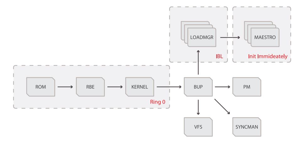
Loading starts with the ROM program, which is contained in the built-in PCH read-only memory. Unfortunately, no way to read or rewrite this memory is known to the general public. However, one can find pre-release versions of ME firmware on the Internet containing the ROMB (ROM BYPASS) section which, as we can assume, duplicates the functionality of ROM. So by examining such firmware, it is possible to reproduce the basic functionality of the initialization program.
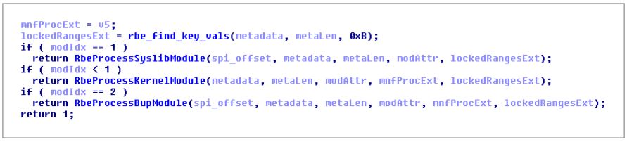
Examining ROMB allows determining the purpose of ROM that is performing hardware initialization (for example, initialization of the SPI controller), verifying the digital signature of the FTPR header, and loading the RBE module located in the flash memory. RBE, in turn, verifies the checksums of the KERNEL, SYSLIB, and BUP modules and hands over control to the kernel entry point.
It should be noted that ROM, RBE, and KERNEL are executed at the zero privilege level (in ring-0) of the MIA kernel.
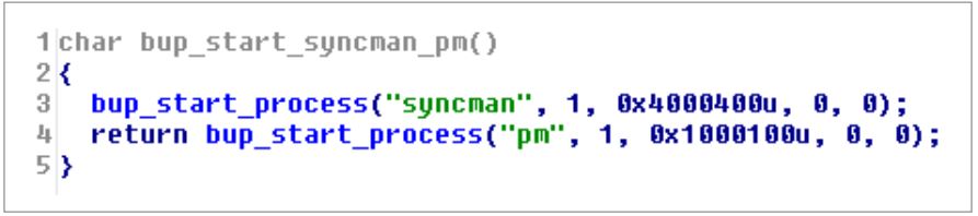
The first process that the kernel creates is BUP, which runs in its own address space in ring-3. The kernel does not launch any other processes itself; this is done by BUP itself, as well as a separate LOADMGR module, which we will discuss later. The purpose of BUP (BringUP platform) is to initialize the entire hardware environment of the platform (including the processor), perform primary power management functions (for example, starting the platform when the power button is pressed), and start all other ME processes. Therefore, it is certain that the PCH 100 Series or later is physically unable to start without valid ME firmware. Firstly, BUP initializes the power management controller (PMC) and the ICC controller. Secondly, it starts a whole string of processes; some of them are hard-coded (SYNCMAN, PM, VFS), and the others are contained in InitScript (similar to autorun), which is stored in the FTPR volume header and digitally signed.
Thus, BUP reads InitScript and starts all processes that conform to the ME startup type and are IBL processes.
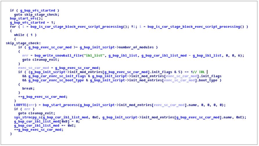
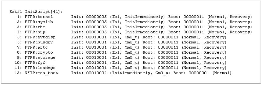
If a process fails to start, BUP will not start the system. As shown in Figure 9, LOADMGR is the last IBL process on the list. It starts the remaining processes, but unlike BUP, if an error occurs during module startup, LOADMGR will just proceed to the next one.
This means that the first way to "slim down" Intel ME is to remove all modules that do not have the IBL flag in InitScript, which will significantly reduce the firmware size. But our initial task was to find out what happens to ME in HAP mode. For this, let us examine the BUP software model.
BRINGUP
If you look closely at how the BUP module works, you can say that a classic finite state machine is implemented inside it. Execution is functionally divided into two components: initialization stages (finite state machine) and execution of service requests of other processes after the system is initialized. The number of initialization stages may vary depending on the platform and SKU (TXE, CSME, SPS, consumer, corporate) but the main stages are common to all versions.
Stage 1
During the initial stage, the sfs internal diagnostic file system (SUSRAM FS, a file system located in non-volatile memory) is created, the configuration is read, and, most importantly, the PMC is queried about what caused the startup: power-on of the platform, restart of the entire platform, ME restart, or waking up from sleep. This stage is called boot flow determination. Subsequent stages in the work of the initialization finite automaton depend on it. In addition, several modes are supported: normal and a set of service modes in which the main ME functionality is disabled (HAP, HMRFPO, TEMP_DISABLE, RECOVERY, SAFE_MODE, FW_UPDATE, and FD_OVERRIDE).
Stage 2
At the next stage, the ICC controller is initialized and the ICC profile (responsible for clock frequencies of the main consumers) is loaded. Boot Guard is initialized and cyclic polling for processor startup confirmation is started.
Stage 3
BUP awaits a message from the PMC confirming that the main processor has started. After that, BUP starts the PMC asynchronous polling cycle for power events (restart or shutdown of the platform) and proceeds to the next stage. If such an event occurs, BUP will perform the requested action between the initialization stages.
Stage 4
At this stage, internal hardware is initialized. Also, BUP starts the heci (a special device designed to receive commands from the BIOS or the operating system) polling cycle for the DID (DRAM Init Done message) from the BIOS. It is this message that allows ME to determine that the main BIOS has initialized RAM and reserved a special region, UMA, for ME, and then proceed to the next stage.
Stage 5
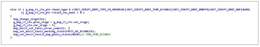
Once the DID is received, BUP—depending on the mode, which is determined by various factors—either starts IBL processes from InitScript (in normal mode) or hangs in a loop, which it can exit only when it receives a message from the PMC, for example as a result of a request to restart or shut down the system.
It is at this stage that we find HAP processing; in this mode, BUP hangs instead of executing InitScript. This means that the remaining sequence of actions in normal mode has nothing to do with HAP and will not be considered. The main thing we would like to note is that in HAP mode, BUP initializes the entire platform (ICC, Boot Guard) but does not start the main ME processes.
SETTING THE HAP BIT
The aforementioned facts help to reveal the second method of disabling Intel ME:
- Set the HAP bit.
- In the CPD section of the FTPR, remove or damage all modules except those required by BUP for startup:
- RBE
- KERNEL
- SYSLIB
- BUP
- Fix the checksum of the CPD header (for more details on the structure of ME firmware, see https://www.troopers.de/downloads/troopers17/TR17_ME11_Static.pdf).
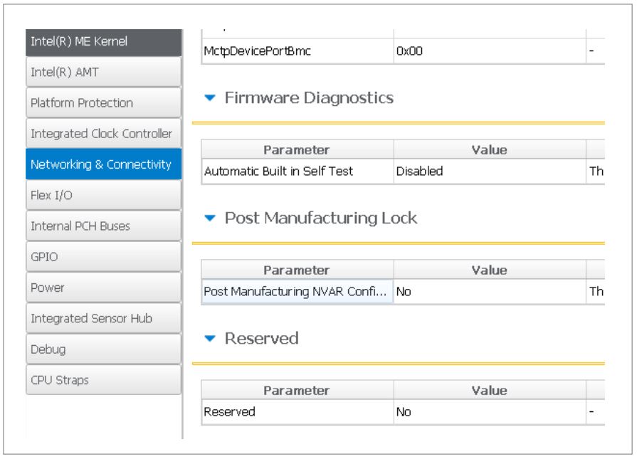
One more question remains—how to set this bit. You can use the FIT configuration files and determine where the bit is located in the image, but there is a simpler way. In the ME Kernel section of FIT, you can find a Reserved parameter. It is this bit that enables HAP mode.
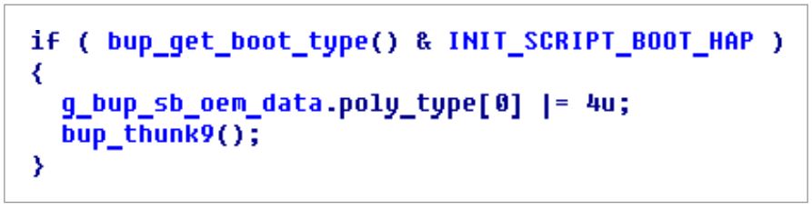
HAP AND BOOT GUARD
We also found some code in BUP that, when HAP mode is enabled, sets an additional bit in Boot Guard policies. Unfortunately, we have not succeeded in finding out what this bit controls.
SUPPORT FOR ME 11 IN ME_CLEANER
While this article was being prepared, the me_cleaner developers updated their utility. Now it also removes all the modules from the images except RBE, KERNEL, SYSLIB, and BUP, but it does not set the HAP bit, which forces ME into TemporaryDisable mode. We were curious to find out what happens with this approach.
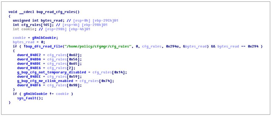
We found that deleting partitions with the ME file system results in an error during reading of the cfg_rules file. This file contains a number of different system settings. Among them, as we believe, is the flag that we called "bup_not_temporary_disable". If this flag is not set, the entire subsystem is switched to TemporaryDisable mode, and since the flag is a global variable initialized by zero, the read error is regarded as a configuration requiring disconnection.
We also checked the firmware of server and mobile versions of ME (SPS 4.x and TXE 3.x). In the server version, this flag is always set to 1; in the mobile version, it is ignored. This means that this method will not work in server and mobile versions (Apollo Lake) of ME.
CLOSING THOUGHTS
So we have found an undocumented PCH strap that can be used to switch on a special mode disabling the main Intel ME functionality at an early stage. We can prove this by the following facts:
- Binary analysis of Intel ME firmware, as described in this paper.
- If we remove some critical ME modules and enable HAP mode, Intel ME does not crash. This proves that HAP disables ME at an early stage.
- We are quite sure that Intel ME is unable to exit this mode because we have not found code capable of doing so in the RBE, KERNEL, and SYSLIB modules.
Similarly, we are sure that the ROM integrated into the PCH is practically the same as ROMB, which also does not contain any code allowing an exit from HAP mode.
Hence HAP protects against vulnerabilities present in all modules except RBE, KERNEL, SYSLIB, ROM, and BUP. However, unfortunately this mode does not protect against exploitation of errors at earlier stages.
Intel representatives have been informed about the details of our research. Their response has confirmed our hypothesis about the connection of the undocumented mode with the High Assurance Platform program. With their permission, we quote Intel's answer below:
"Mark/Maxim,
In response to requests from customers with specialized requirements we sometimes explore the modification or disabling of certain features. In this case, the modifications were made at the request of equipment manufacturers in support of their customer’s evaluation of the US government’s “High Assurance Platform” program. These modifications underwent a limited validation cycle and are not an officially supported configuration."
We believe that this mechanism is designed to meet a typical requirement of government agencies, which want to reduce the possibility of side-channel leaks. But the main question remains: how does HAP affect Boot Guard? Due to the closed nature of this technology, it is not possible to answer this question yet, but we hope to do so soon.
Mark Ermolov, Maxim Goryachy